There is no doubt that photovoltaic modules are one of the most important equipments of photovoltaic power plants. Today, the commonly used polysilicon photovoltaic modules include: key parameters of photovoltaic modules, hot-spot effects and PID effects, and post-operation detection.
I. Key parameters in the technical specifications of photovoltaic modules
1, power
We often say that we use 255Wp PV modules. The “p†in the table below is an abbreviation for peak, which means its peak power is 255W. All technical specifications are marked with "standard test conditions." The following figure shows part of Changzhou Tianhe's PV module specification (250W, the same below).
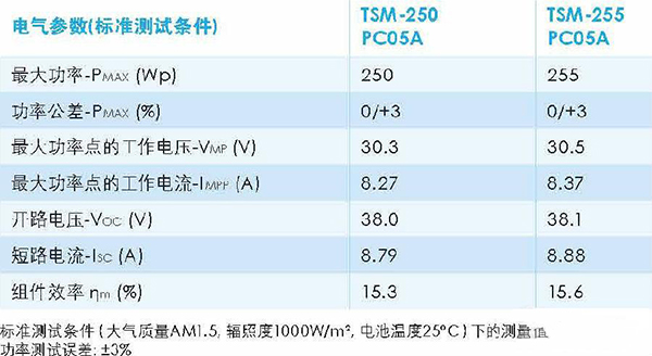
Only in the standard test conditions (irradiance 1000W/m2, battery temperature 25 °C), the output power of the PV module is the "nominal power" (250W), the power will certainly change when the irradiance and temperature change. In addition, the power error is plus or minus 3%, indicating that the actual power of the component is an increase from 242.5 to 257.5W. However, the power deviation of this component is a positive deviation of 3%.
In non-standard conditions, the output power of photovoltaic modules is generally not the nominal power, as shown below.
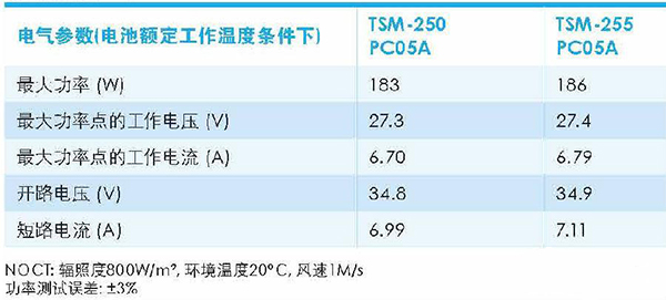
When the irradiance is 800W/m2 and the battery temperature is 20°C, the output power of the 250W module is only 183W, which is 73.2% of the standard.
2, efficiency
In theory, the same size, nominal power components, the efficiency is certainly the same. Photovoltaic modules are composed of solar cells. A photovoltaic module usually consists of 60 (6×10) or 72 (6×10) cells, with an area of ​​1.638 m2 (0.992m×1.652m) and 3.895 m2 (0.992m) respectively. × 1.956m).

When the irradiance is 1000 W/m2, the power received on the 1.638 m2 module is 1638 W. When the output is 250 W, the efficiency is 15.3%, and it is 15.6% at 255 W.
3, voltage and temperature coefficient
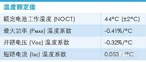
The voltage divides the circuit voltage and the MPPT voltage, the temperature coefficient divides the voltage temperature coefficient and the power temperature coefficient. When designing series and parallel schemes, the open circuit voltage, operating voltage, temperature coefficient, and local extreme temperature (preferably during daytime) are used to calculate the maximum open circuit voltage and MPPT voltage range to match the inverter.
Second, the two effects of photovoltaic components
Hot Spot Effect
A solar cell module that is shielded in a series branch will be used as a load to dissipate the energy generated by other light-emitting solar battery modules. The shaded solar battery module will heat up at this time, which is the hot spot effect.
This effect can severely damage solar cells. Some of the energy generated by illuminated solar cells can be consumed by shaded batteries. The hot spot effect may only be a piece of guano.
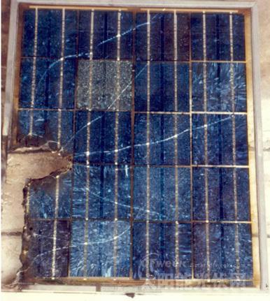
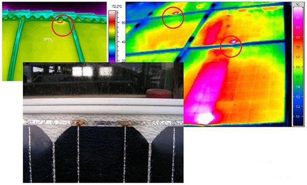
In order to prevent the solar cell from being damaged due to the hot spot effect, it is preferable to connect a bypass diode in parallel between the positive and negative electrodes of the solar cell module so as to prevent the energy generated by the illumination device from being consumed by the shielded component. When the hot spot effect is severe, the bypass diode may be broken down, causing the component to burn out, as shown below (pictures from TUV-Rheinland).

2, PID effect
(Refer to He Baohua et al. "Crystalline silicon photovoltaic module anti-PID technology" content)
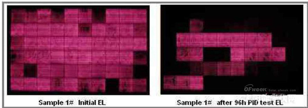
PID (Potential Induced Degradation) is a battery component that is subject to high voltage for a long period of time, which causes leakage current between the glass and the package material. A large amount of charge slams on the surface of the battery slice, which deteriorates the passivation effect of the battery surface and causes the component to deteriorate. Performance is lower than the design standard. When the PID phenomenon is serious, it will cause a component power to attenuate more than 50%, thereby affecting the power output of the entire string. The PID phenomenon is most likely to occur in high temperature, high humidity, and high saline-alkaline coastal areas.
The main reasons for the PID phenomenon of components are as follows:
1) System Design Reasons: Lightning protection grounding of photovoltaic power plants is achieved by grounding the components of the edge of the square array. This creates a bias between the individual components and the frame. The higher the bias voltage of the components, the PID phenomenon occurs. The more serious. For the P-type crystalline silicon module, the negative polarity of the module frame relative to the battery plate is effectively prevented from occurring due to the negative pole of the inverter of the transformer, but the negative electrode grounding of the inverter will increase the corresponding system construction. cost;
2) Photovoltaic module causes: The external environment of high temperature and high humidity causes a leakage current between the battery plate and the grounding frame, and a leakage current path is formed between the packaging material, the back plate, the glass, and the frame. The use of changing the insulating film Ethylene vinyl acetate (EVA) is one of the ways to achieve the component anti-PID. Under the condition of using different EVA packaging films, the anti-PID performance of the components will be different. In addition, the glass in photovoltaic modules is mainly calcium-sodium glass, and the influence of glass on the PID phenomenon of PV modules is still not clear.
3) Battery Cause: The uniformity of the cell sheet resistance, the thickness of the antireflection layer, and the refractive index all have different effects on the PID performance.
In the above three aspects that cause PID phenomenon, the component PID phenomenon caused by the potential difference between the component frame and the component inside the photovoltaic system is recognized by the industry, but the mechanism that causes the component to generate the PID phenomenon in both the component and the battery is not yet Clearly, the corresponding measures to further improve the anti-PID performance of the components are still unclear.
Third, the performance of photovoltaic modules
After the photovoltaic power station is running for a period of time, it needs to be tested to determine the performance of the photovoltaic power station. Involving photovoltaic modules mainly includes the following items.
1, power attenuation test
What is the decay rate of PV modules after 1 and 25 years of operation? For 25 years too long, there may not be a power station that has been operating for such a long time. According to national standards, the decay rate of crystalline silicon cells for 2 years should be within 3.2%. However, this data is really hard to say for three reasons:
1) The output power of PV modules is calibrated with laboratory standard light sources and testing environment, but it seems that there are certain differences between the standard light sources of different manufacturers in China. The 250W component that was calibrated at the A plant went to the B plant, which may be the 245W component.
2) The accuracy of the instruments used in field tests is poor, and it is said that errors within 5% are acceptable. Using an instrument with an error of 5%, the attenuation of 2% (1 year) is measured, and the difficulty is somewhat large, and the result is doubtful.
3) The difference between the test conditions at the site and the laboratory is quite large, and the time at 1000W/m2 and 25°C is too small! Therefore, it is necessary to perform a conversion from the test value to the standard value, and the output power and irradiance are only positively correlated in a very small interval. As shown in Fig. 2, even at 800 W/m2, it is not positively correlated. Therefore, there must be errors in the conversion.
In addition, many components may appear to be -3% power deviation, not decay, 3% will be lost directly ... ...
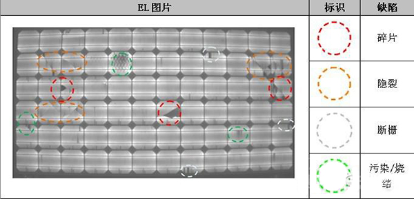
2, EL test
When there is a problem with the photovoltaic module, the local resistance increases and the temperature in the area rises. The EL tester is just like the X-ray machine in our physical examination. It can perform physical examination on the PV modules. Through infrared images, according to different temperatures, the images show different colors, which makes it very easy to find many problems of PV modules: cracking. , hot spots, PID effects, etc.
Photovoltaic modules are easy to be stepped on and bumped during transport, handling, installation, etc., resulting in unobvious cracking of components and greatly affecting the output power of the module. It can be detected by EL change, as shown below.
The photo below shows the infrared image of the hot spot phenomenon (picture from TUV-Rheinland). The red dot is where hot spots occur.
The following figure shows the infrared photo of the PID effect. The cells with serious PID effect are blackened.
In addition to the above monitoring, the visual inspection of the components is also very important. Such as back scratches, yellowing, bubbling, and connector dropout of components.
Food Grade Salt produced from Sea Salt gives a slightly different taste than Table Salt produced from Rock Salt, and is believed to be better from ordinary table salt in taste and texture. It can serve as a good substitute to regular table salt because, although it lacks sufficient iodine, it contains several other healthy minerals not found in table salt, including potassium, magnesium, calcium, and sulfate. We produce an A+ Food Grade Sea Salt was human consumption.
Edible Grade Sea Salt,Edible Iodized Sea Salt,Food Grade Sea Salt,Iodized Sea Salt
Weifang Xinchang Chemical Co.,Ltd , http://www.xinchangchem.com