I. Commonly used cable laying methods for photovoltaic systems
The laying of the cable is divided into the clear and dark. For photovoltaic power generation systems, commonly used cable laying methods include: direct laying, laying of protective tubes, laying of cable trenches, and laying of cable trays.
1.1 General Rules for Cable Laying
1. The route selection of cables should meet the following requirements:
(1) Cables should be protected from mechanical external forces, overheating, and corrosion.
(2) Under the conditions of meeting the safety requirements, the shortest cable path shall be ensured.
(3) It should be easy to lay and maintain.
(4) It is advisable to avoid places where construction will be excavated.
2, the cable in any laying method and all the path conditions change parts up and down, should meet the cable allowable bending radius requirements.
3. When the number of cables in the same channel is large, if it is laid on a multi-layer bracket on the same side, the order of voltage from high to low and from bottom to top should be met. Voltages of the same voltage level should be laid on the same layer.
4. The arrangement of the cable arrangement on the same layer of the bracket, the power cable should have 1 times the gap of the cable outer diameter, and should not be stacked.
5. In closed cable channels such as tunnels, trenches, shallow troughs, vertical shafts, and mezzanines, no heat pipelines shall be installed, and no flammable gas or flammable liquid piping shall be allowed to pass through.
6. Non-outdoor cables other than overhead insulated cables should be shaded by covers and covers when used outdoors.
1.2 Cable laying method
The choice of cable laying method should be based on the engineering conditions, environmental characteristics, cable type, quantity and other factors, as well as the principle of reliable operation, easy maintenance and technical and economical rationality.
1, buried directly
2, protective tube laying

When the cable intersects the road or railway or needs to pass through the wall, the protective pipe laying method should be used.
3, cable trench laying

4, slot tray installation
The same path does not interfere with the required wiring and can be laid in the same metal tube or metal box. The total cross-sectional area of ​​the wire in the metal conduit or metal box should not exceed 40% of its cross-sectional area, and the current-carrying wire in the metal box should not exceed 30 wires.
When non-power loop wires such as control and signal are laid in the same metal conduit or metal box, the total cross-sectional area of ​​the wire should not exceed 50% of its cross-sectional area.
When cable trays and ladder frames are laid horizontally, the best span should be selected according to the load curve, and the spacing between supporting points should be 1.5m to 3m. When laying vertically, the spacing between the fixed points should not be more than 2m.
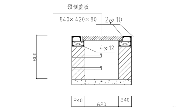
The buried cable is in accordance with the requirements of the code. After the digging of the cable trench is completed, the sand cushion is laid on the bottom of the trench, and the debris in the trench is removed and the cable is laid. After the cable is laid, the sand must be filled immediately. The cable is covered with a layer of bricks or concrete panels to protect the cable and then backfilled with a cable laying method.
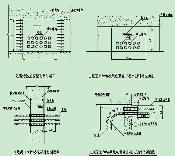
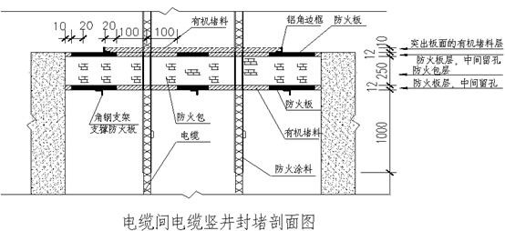
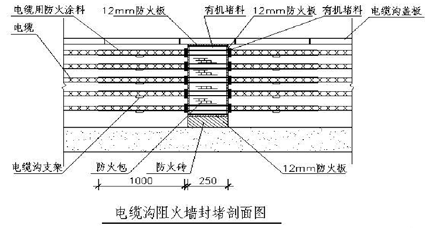
Second, the cable laying fire blocking practices
Fireproof plugging is used to block various penetrators, such as cables, ducts, tubing, air pipes, etc., through various openings formed when wall (store) walls, floor (A) boards are formed, and fireproof partitions of cable trays to avoid fire. Spread through these openings and gaps.
The commonly used cable laying fire prevention plugging method of photovoltaic power generation system summarized and collected by Li Bao Waterfall Energy Engineering (Shanghai) Co., Ltd. during construction is as follows:


GF20/GF20CNC/GF25CNC Automatic Rebar Stirrup Bending Machine can bend round steel bar with diameter to various geometrics shape as required by construction.
Main Features Of Rebar stirrup bending machine
1. Convenient use: perfect safety performance, standard angle, fast speed, light and
handy.
2. Easy Operation: one man can operate it once switch on the power.
3. Convenient of range adjustment: for GF20 model, just need to shift induced magnet.
for GF20 CNC and GF25CNC model, just need to press the button on operation panel
4. We adopt two foot pedals: 90°and 135°, angle adjustment freely.
5. Fast Speed: rotate speed is 20-25 times/min (GF20), 25-30 times/min(GF25).

Main Technical Parameter
| Item | GF20 | GF20CNC | GF25CNC |
|
Voltage |
3-380V-50HZ or others |
3-380V-50HZ or others |
3-380V-50HZ or others |
|
Motor Model |
Y90L-4 |
Y90L-4 |
Y100L2-4 |
|
Motor Power |
2.2KW | 2.2KW | 3.0KW |
|
Motor Speed |
1440r/min | 1440r/min | 1440r/min |
|
Bending Common Carbon Steel |
Φ4 – Φ20 |
Φ4 – Φ20 |
Φ4 – Φ25 |
|
Bending Deformed Bar |
Φ5 – Φ16 |
Φ5 – Φ16 |
Φ5 – Φ20 |
|
Weight(kg) |
92±5 |
92±5 |
92±5 |
|
Dimension (mm)(L*W*H) |
800×520×820 |
800×520×820 |
800×520×820 |
Rebar Stirrup Bending Machine
Automation Rebar Stirrup Bending Machine,Hand Operated Rebar Bending Machine,Construction Material Rebar Bending Machine,Used Hydraulic Rebar Bending Machine
BAODING JINDI MACHINERY CO., LTD , https://www.rebarconnector.com