1. No rivet riveting technology application and working principle
1.1 Industry application without rivet riveting technology
Since its inception, rivet-free riveting technology has been widely used in various industries such as automobiles, aerospace, marine, air-conditioning, and television, and has shown strong advantages.
For example, the copy machine stand of Japan Minolta; the fan case of Ziehl-Abegg in Germany; the Apple computer case of the United States; the outer hub of the dentist machine, the subject of the washing machine, the door of the refrigerator; the connection of the workpiece of the Bosch-Simens microwave oven and the top cover of the dryer .
The application of this technology in automobiles is mainly divided into two areas: one is applied to the surface covering parts of the body-in-white, such as aluminum body, door, front and rear cover and top cover; the second is applied to some automobile parts, such as shaking Window machine, roof window, lamp guide, etc.
At present, in the cars produced by many well-known automobile manufacturers at home and abroad, the application of non-rive connection technology can be seen, such as: Mercedes-Benz and BMW series models abroad; Audi A6, Sagitar, etc. of FAW-Volkswagen; Touran of Shanghai Volkswagen , polo, etc.; Shanghai GM's new Grand Hyatt, the new Regal series, etc.; FAW car's new Pentium B70; Shandong Shifeng, Shandong Juli, Anhui Feicai and other companies' agricultural car panels and so on.

Volkswagen hood inner panel assembly - Shanghai Volkswagen Automotive Co., Ltd.
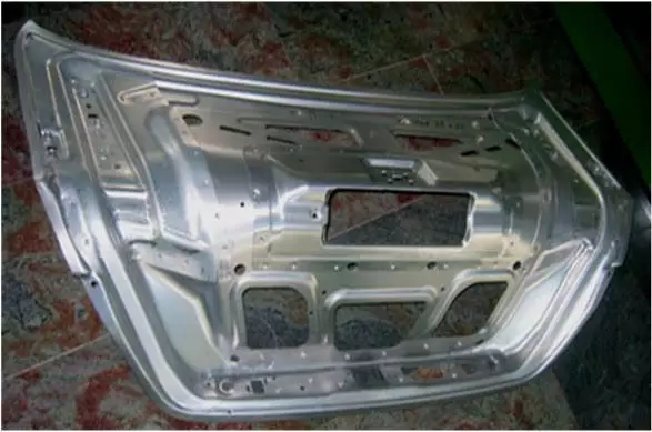
New Pentium B70 luggage inner panel assembly - Auto Car Co., Ltd.
1.2 The main working principle of rivet-free riveting technology
The rivet-free riveting technology is a stamping point connection technology for plastic thin plates. The connection points are non-detachable. The main working principle is: using a pressure device and a connecting mold, through a short-time high-pressure machining process, the plate itself The materials are cold-extruded and plastically deformed to each other to form plastic deformation points, so that two or more layers of different thicknesses of different materials form a joint point at the extrusion, and the pieces are connected.
Taking the die straight wall integral joint as an example, the entire riveting process can be divided into five stages:
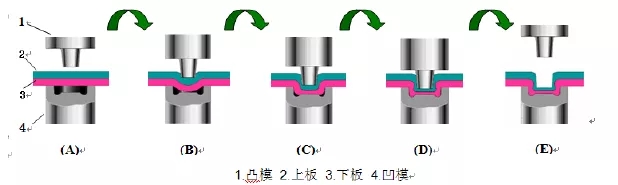
No rivet riveting stamping process simulation
Preparation stage (Figure A): Before joining, the punch and the die are in place, the axes are concentric, and the axis should be perpendicular to the plane of the plate to prevent damage to the mold.
Initial stage (Fig. B): At this stage, the punch is contacted and pressed into the upper plate until the lower plate contacts the die side. During the upper plate and the lower plate, tensile plastic deformation gradually occurs, forming a joint at The basic outline of the upper side of the plate.
Forming stage (Fig. C): The punch continues to descend, and the sheet metal material flows into the groove of the die until it approaches the dead point at the groove. In this process, the inverted conical structure of the punch and the pressure between the plate, the punch and the die prevent the metal material from flowing upward, and finally the metal material flows to the groove of the die to form the upper and lower plates to engage each other. status. In terms of type, a rivet-free riveted joint is basically formed.
Strengthening stage (Fig. D): After the rivet-free riveted joint is formed, it will continue to maintain a certain pressure. On the one hand, it will prevent the rebound of the sheet, and the material will be fully filled to ensure the shape of the riveted joint. On the other hand, it can be refined by cold working and fine-grained. Granules improve the mechanical properties and load carrying capacity of the joint. At this point, the rivet-free riveted joint is finally formed in terms of form and strength.
Demolition stage (Fig. E): After the riveted joint is formed, the punch is advanced and the mold is removed. If it is necessary to rive the next riveting point in the production process, the upper and lower molds must be completely removed before the mold can be moved to the next riveting point to avoid damage to the mold.
2. No rivet riveting technology evaluation
The rivet-free riveting technology has significant advantages over the traditional rivet riveting and spot welding methods in terms of quality, cost, energy saving and environmental protection of automobile manufacturing. At the same time, there are also some shortcomings.
2.1 Advantages compared to the traditional rivet riveting process
Shortened process: The traditional rivet riveting process and the rivetless riveting process are shown below.
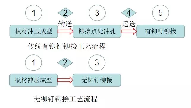
As can be seen from the comparison above, the rivet-free riveting process can save up to 2 steps compared to the traditional riveting process, which can save a lot of fixed investment, labor costs and production sites.
Reduced investment in raw materials: the traditional rivet riveting process is less than the rivet riveting process. Each joint requires more than one rivet. The new B70 rear cover inner panel is always an example. The bicycle has 21 joints and is rivetless. The process saves 21 rivets per car than the traditional rivet riveting process. 200,000 cars can save 4.2 million rivets, greatly reducing material costs.
The advantages of light weight are obvious: if the connection point of the same body assembly is rivet-connected, the body assembly additionally increases the weight of the rivet after the joint is formed, and the rivet-free riveting process is adopted, because no material is added or subtracted, so no additional increase is made. The weight of the body assembly has obvious advantages in weight reduction.
Other advantages: Compared with the traditional rivet riveting process, the rivet-free riveting process has many advantages. For example, the fatigue strength of the former connection point is higher, while the fatigue strength of the latter connection point is relatively low, which is easy to be caused by vibration during driving. And the loose; the former connection joint appearance rules, seamless, beautiful, and the latter looks relatively poor.
2.2 Advantages compared to spot welding process
The fatigue joint strength is high: the spot weld joint is formed by hot working, the weld zone is solidified after the base metal is melted, and the internal and external cooling speeds are different, which causes the stress concentration at the weld joint to be large, and the stress corrosion is easy to occur. The local grain of the joint is coarse, and small defects such as holes are generated. Such a variety of structures are very hard and brittle and easily broken, which greatly reduces the fatigue strength of the joint, thereby causing a decrease in joint life. The rivet-free riveting is performed by cold working mechanical extrusion and metal flow forming. The transition at the joint is relatively smooth. The base material does not affect the internal composition of the material due to melting. The internal crystal grains are relatively thin and there is no large stress concentration, so there is no The fatigue strength of the rivet riveted joint is higher than that of the spot welded joint. According to the technical data provided by TOX, the fatigue strength of the rivet-free riveted joint is about 2-3 times that of the spot welded joint.
Suitable for lightweight materials: In the background of lightweight body, the use of high-strength, lightweight materials to reduce the weight of the body is the mainstream direction of lightweight, such as aluminum alloy, aluminum-magnesium alloy and other materials. For the connection of these light metal materials, the spot welding process is prone to large problems in terms of equipment energy consumption, wear and tear, joint quality, etc., and the rivet joint can completely avoid the above problems of spot welding technology through cold working mechanical stamping technology, realizing the light metal Effective connection of materials.
In addition, for lightweight bodies with higher strength and stiffness requirements, it can also be achieved by the combination of rivet riveting and bonding. As shown in the figure below, part of the bodywork of the AUDI TT lightweight hybrid body is manufactured in a combination of rivet-free riveting/adhesive.
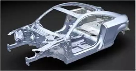
AUDI TT lightweight hybrid body
Suitable for sandwich structure connection: in the manufacture of automobiles, due to the process requirements, some non-metallic materials such as textiles, plastics, films, foils, papers, etc. need to be added between the metal plates, which are hot-melted by spot welding and then solidified. The method is difficult to realize the connection of the joint, but the mechanical cold processing method without rivet riveting can realize the joint of the above sandwich structure with high quality.
Appearance quality advantage: After the spot welding head is formed, the surface has dark indentations, and many are accompanied by splashing and slag generation, especially for surface-coated metals, the surface layer of the joint has been completely destroyed. The appearance is not beautiful, and individual needs to be repaired manually. After the rivet-free riveted joint is formed, it exhibits a regular bump state or a flat point state. For the surface plating and the painted metal, the plating of the metal surface after the joint is formed, the paint, etc. are not damaged or damaged. Therefore, the appearance quality of the rivet-free riveted joint is much better than that of the spot welded joint. In addition, the traditional body manufacturing process is first post-weld coating, and the rivet-free riveting technology does not hurt the paint coating. This process makes it possible to reverse the process.
Body size accuracy control advantage: When the spot welding head is formed, it is affected by welding heat and electrode pressure, and the plate near the welding spot is deformed to different degrees; the rivet riveting technology is cold working, the plate does not produce thermal deformation, and its convex and concave die and plate There is a certain contact area to ensure that the sheet near the joint is not mechanically deformed. This advantage is very beneficial to the dimensional accuracy control of the body.
Safety and environmental advantages: Spot welding heads are accompanied by sparks, splashes, CO2 fumes and electromagnetic radiation during the molding process. Long-term exposure can seriously pollute the environment and personal safety, especially during the summer when the operator is working. Also have to wear a variety of heavy labor insurance products to reduce or avoid the adverse effects of spot welding. In the molding process, the rivet-free riveted joint can completely avoid these pollutions, and the whole connection process does not emit light, splashes, CO2 soot and electromagnetic radiation. Therefore, the nailless riveting technology is much better than the spot welding connection technology in terms of safety and environmental protection, which is more conducive to the sustainable development of the automotive industry and has broad prospects.
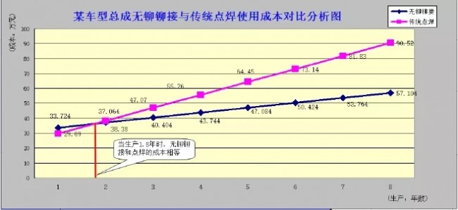
The cost advantage of long-term use: no rivet riveting equipment investment and the cost of punch and die consumables are higher than spot welding, the energy consumption is much lower than spot welding, the former's power source is mainly gas, and the latter's power source It is mainly water, gas and electricity. After a certain period of use, the total cost of the rivetless riveting process will begin to be lower than the spot welding process cost. Taking the inner panel of the trunk lid of a certain model of a company as an example, it is calculated that after the rivetless process is put into use for nearly two years, the total cost starts to be lower than the cost of the spot welding process, and the cost advantage gradually appears.
2.3 Inadequacies in rivet-free riveting technology
Compared with the traditional rivet riveting and spot welding technology, the rivet-free riveting technology has many advantages as well as many disadvantages:
Compared with the traditional rivet riveting technology: First, the rivet-free riveting technology requires relatively high requirements on the process conditions required for implementation, and it is not easy to achieve two or more non-metallic sheets with very poor plasticity as in the former. The second is that there is no restriction on the combined thickness of the connecting plate without rivet riveting. If it is too thin or too thick, it is difficult or impossible to form a riveted joint; therefore, in theory, the connection success rate without the rivet riveting process is lower than that of the ordinary riveting.
Compared with spot welding technology: the disadvantages of rivet-free riveting technology are as follows: First, its static strength is not as high as spot welding. According to TOX research, the static strength is about 70% of spot welding, so it is subject to strong body parts. For applications such as floor assemblies, the industry continues to conduct research and exploration. Second, for steels with high hardness or heat-hardened steel, it is difficult to form riveting directly because it is difficult to form good plastic flow and connection.
3. No rivet riveting process design
The rivet-free riveting technology requires detailed process in application. The production preparation of the process is quite different from the traditional spot welding process. Many things need to be paid attention to before and after the process is formulated. Many conditions are met, and slight deviation will affect the process. Rationality and operability, even bring greater time and economic losses.
3.1 Preparation
The 3D product data output by the product department is prepared to carry out the simulation of the rivet-free riveting process, the synchronous process review of the product data, and the selection and quantity determination of the riveting equipment.
Prepare the 2D product data output by the product department to clarify the number, shape, strength, etc. of the connection points, determine the metrics for the connection points, and determine the riveting test for the riveting parameters.
Prepare the planning department for the annual production and life cycle planning of the model to determine the production cycle of the riveting process and determine the number of riveting equipment.
Prepare the process position, area planning, comprehensive production cycle and riveting equipment quantity and selection information of the process department, and carry out the detailed layout work of the riveting process.
Prepare the metal material with the same material, the same thickness, and the same manufacturer for tensile and shear tests to determine the detailed process parameters required for the formation of qualified riveted joints; only with the above conditions, after comprehensive consideration and analysis In order to complete the formulation of the riveting process plan.
3.2 Conducting process reviews in synchronization with product design
After receiving the product documents before the trial production of the product department, the product data should be reviewed from the aspects of sheet material, sheet layer thickness, sheet thickness, combination order, riveting point size, riveting point position, etc., combined with the company's process area. The actual situation such as cost control puts forward the review opinion of the process department for the product structure that is not suitable or does not meet the rivet riveting process conditions, so that it is suitable for the riveting process. Change the effect to verify when the product is trial-produced.
The process review is very important. The content and quality of the review directly determines whether the riveting process can be realized, how easy it is to achieve, and its investment cost.
Material evaluation of the sheet material: During the riveting process, the material undergoes severe deformation and plastic flow at the jointed portion, and the plastically poor material is relatively easily broken during the joining process. Therefore, the rivet-free riveting requires a certain elongation of the material to be joined. At the same time, if several pieces of material with excessive elongation are combined and riveted, the joint quality will be unsatisfactory. For this, it is necessary to submit corresponding evaluation opinions to the product department.
Plate layer evaluation: No rivet riveting technology can be applied to two types of plate combinations of two layers, three layers and intermediate interlayers. The most common application is the riveting of two layers of plates. The riveting of the three-layer board is difficult in terms of cost control or quality control.
Therefore, if there is no special situation, it is necessary to recommend that the product department try to avoid the design of the three-layer riveted structure in the review, and try to use the two-layer riveted structure design. In addition, if the structural strength of the product is required to be high, a structure in which a bonding adhesive is applied between the two layers can be used.
3.3 Sheet thickness review
The requirement for the thickness of the rivet-free riveting is: usually the minimum thickness of the single plate is about 0.3 mm, the maximum combined plate thickness is 8 mm, and the thickness of individual aluminum, copper and other non-ferrous metals can reach 11 mm. However, in the case of special circumstances, such as the thickness of the product that is required to exceed the limit, it is finally possible to determine whether the thickness can meet the requirements through experiments.
3.4 Upper and lower order review of sheet combination
For plates of different thicknesses, the combination of the thick plate and the lower plate is preferred, that is, the thick plate is on the convex side of the riveting device, and the thin plate is on the concave side of the riveting device. After forming, the convex point is from the thick plate to the thin plate. Protruding. If there is no special case, do not place the sheet on the side of the punch, because the sheet on the side of the punch is stretched longer, so that the sheet has a risk of cracking.
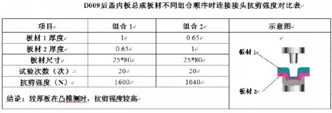
Taking the inner panel of D009 back cover as an example, the thickness of the reinforcing plate is 1mm, the thickness of the inner plate is 0.65mm, the punch is on the side of the reinforcing plate, and the direction of the bump is protruded from the reinforcing plate toward the inner plate, as shown in Figure 6 below:

D009 back cover inner panel assembly riveting plate combination sequence diagram
At the same time, the thick plate is placed on the side of the punch and the joint formed by the thin plate on the side of the punch. Compared with the tensile effect of the material, the thickness of the neck formed by the former is thicker than the latter, and the joint formed by the former is at the shear strength. The aspect is far stronger than the latter.
The following table shows the comparison of the shear strength of different combinations of sequential joints of the inner panel of the trunk lid of a model:
3.5 Plate thickness combination type review
In the assembly of a body part, when a plurality of single pieces are respectively connected to the single piece of the parent body, the thickness of the plurality of pieces of the single piece must be the same as possible to reduce the thickness combination type.
Taking the D009 back cover inner plate as an example, both the hinge reinforcing plate and the lock reinforcing plate are connected to the inner plate. The thickness of the plate of the lock reinforcing plate and the hinge reinforcing plate is the same, both being 1 mm, mainly because if the thickness of the two is inconsistent, There will be two different combinations, so that the lateral interference between the mold and the plate is different when riveting. If the interference is appropriate, sufficient plastic flow can be generated during the press connection to inlay each other to meet the strength requirement. If the interference is not appropriate, the joint strength will be reduced.
Therefore, if the thickness of the two plate combinations differs greatly, and only the riveting die is selected according to one of the combinations, the strength of the riveted joint of the other combination is greatly reduced, and in severe cases, the mold is damaged, resulting in unnecessary loss.
If each type of mold is selected according to its own mold, it will increase the purchase quantity of materials such as molds, riveting tongs, and robots, and the cost, the beat, and the production area will be lost. Therefore, in carrying out this review work, it is necessary to minimize the thickness combination of the plates to minimize the number of riveting equipment.
3.6 Riveting point diameter, bottom thickness, height, quantity review
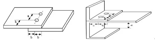
Riveting point diameter. Generally refers to the outer diameter of the bump of the die side plate, as shown in Figure 7 "a". The larger the diameter of the joint, the higher the shear and tensile strength. The more commonly used diameters are Ф3, Ф4, Ф5, Ф6, Ф8, Ф10, Ф12. When selecting the diameter of the joint, on the one hand, it should be based on the principle of product strength requirements. On the other hand, it must be noted whether the diameter can be realized in position and space.
The riveting point is thick at the bottom. It refers to the distance between the upper surface of the plate at the bottom of the riveting point and the lower surface of the plate at the bottom of the riveting point, as shown in the figure "b". The reference value is determined by the riveting test. Within the tolerance range allowed by the reference value, the smaller the "b", the lower the tensile strength, and vice versa. Controlling the thickness of the bottom can control the strength.
Riveting point height. Refers to the vertical distance between the outer surface of the lower plate at the bottom of the riveting point and the lower surface of the lower plate that is in contact with the end face of the die. As shown in Figure 7, the height of the "c" boss is higher and the material is stretched. The larger the amount, the thinner the neck thickness and the bottom thickness, and the corresponding shear strength and tensile strength are smaller. However, if the height of the boss is too small, the setting of the upper and lower sheets may be difficult or the setting may be insufficient. Therefore, the height of the boss also has a reference range, and the reference value needs to be confirmed by a riveting test.
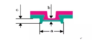
Riveting point diameter, height, low thickness
The number of riveting points. Refers to the number of riveting points on one assembly. When connecting between plates, it is necessary to avoid using single-point connection. When there is a large torque acting on the single point of the plate, there will be a strong rotation trend at the joint. This makes it easy to fail at the joint.
3.7 Riveting point position review
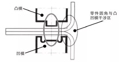
The rivet-free rivet and the spot welding tong have similarities in the overall structure. For example, there are C-type and X-type points, all of which have parameters such as throat and throat width; however, there are obvious differences in fine structure, such as welding. The fixed side and the moving side of the clamp and the contact end of the part are the electrode caps, and the corresponding positions of the rivet tongs are the convex and concave molds; the tongs on the convex side of the rivet are equipped with the stripper, and in the simulation, it is necessary to recognize the The interference area between the parts, the following figure shows the basic structure of the C-type rivet:

C line riveting is enough
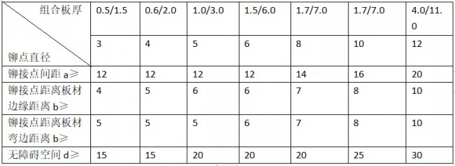
The spacing between the riveting points is reviewed. The spacing between the riveting points is the dimension a in Figure 9. In order to avoid mutual influence between the two riveting points, there should be a certain spacing between the connecting points, and the thickness of the connecting plate combination is different, the connecting points are different in diameter, and the riveting points are The spacing requirements are also different. Table 3 below is TOX's positional requirements for different combinations of thickness and diameter riveting points. It can be used for reference during the review.
The distance between the riveting point and the edge of the sheet is reviewed. The dimension refers to the distance between the center of the riveting point and the edge of the plate. Considering that the riveting tongs and the die must be in full contact, the center of the riveting point must be kept at a certain distance from the edge of the plate. The illustration and requirements are shown in the following figure and the following table. Size b.
Judging the distance between the riveting point and the plate flange. The size refers to the minimum distance between the center of the riveting point and the flange of the plate (for the hemming structure, attention must be paid to the influence of the hemming radius on the convex and concave mold), taking into account the need to avoid interference between the riveting die and the demoulder and the part, riveting The center of the point must be kept at a certain distance from the nearest flange. The illustration and requirements are shown in Figure IX and Table 3 for size c.
Complex spatial structure review. That is to say, for the combination of parts of the structure with complicated operation space, it is necessary to consider the interference between the tongs and the parts of the rivet clamp, and the drawings and requirements are shown in the following figure and the dimension d in the table.
Position requirements for riveting points for different combinations of thickness and diameter
Ordinary lap joints and hem joints with hem stitches

D009 back cover inner plate riveting simulation diagram
3.8 Formulation of riveting process parameters
After the riveting equipment has been determined, the detailed process parameters of the riveting shall be established to ensure a qualified connection point. The main riveting parameters must be determined by performing a special riveting test.
Prepare before the test. First, prepare the hardware materials: test material. The material must be selected and later used for official production of sheet materials, the same manufacturer, the same thickness, 20 pairs of each combination, cut into 80*20 regular material; second, ready software information: product documentation. The requirements of the riveting point, such as the diameter, height and strength of the riveting point, must be clearly reflected in the document.
Riveting test. After the above materials are prepared, the slabs are riveted without rivets, and the parameters of the riveting process are obtained through mechanical tests such as shearing and stretching, such as bottom thickness control parameters, punching pressure, mold release force, mold combination, etc. Relevant data, with the aim of product documentation requirements, continuously analyze and correct the parameters during the test, and select the word data that best meets the product requirements.
The tensile test piece and the shear test piece are lapped as shown in the following three figures. After the rally test piece is riveted, the test piece is bent to prepare for the tensile test.

Tensile test piece lap joint form shear test piece lap joint form
After the riveting test is completed, the process parameters of riveting can be started.
Bottom thickness control parameters. It is the most important parameter for controlling the quality of the riveting point, and the measurement is simple. Its reference value is determined by the riveting test, and the deviation range is ±15% of the reference value. Under the condition that the workpiece material and thickness are certain and the mold is fixed, the control parameters have a corresponding relationship with the pressing force at the time of connection. The higher the punching pressure, the smaller the control parameter value; conversely, the lower the punching pressure, the larger the control parameter value.
Punching pressure. It is divided into the punching force required for the joint forming and the maximum punching pressure allowed by the die. The former must not exceed the latter when the punching pressure (working oil pressure) is set, otherwise the mold will be damaged. When commissioning the production line, the pressing force required for the connection should be initially set according to the value of the riveting test output, and then the difference between the bottom thickness reference value and the riveting test can be obtained each time the thickness of the bottom thickness is formed during the commissioning process. The correction is made to finally form the pressure parameters that meet the actual site conditions. The maximum punching force of the mold is generally given by the rivet cutter manufacturer.
The gap between the male and female molds when clamping. When the embossing die is idling without a workpiece, the punch and the punch are easily in direct contact and mutually squeezed, causing hidden troubles such as deformation and breakage of the die; thus, it is necessary to ensure that the embossing die is closed in the idling mode. There is a certain gap value, which can be set by the control system. The setting interval is: greater than zero and less than the bottom thickness reference value of the joint.
4. No rivet riveting quality control
After the rivet-free riveting process is put into production, the quality of the riveting joints needs to be tested and monitored to ensure the quality and stability of the joints.
4.1 Inspection and control of appearance quality
Number and location of riveting points. After the riveting of each part assembly, it is necessary to manually check whether the number of riveting points meets the requirements of the product; whether the direction of each riveting point meets the product requirements.
The appearance of the riveted joints was visually observed. Visually visualize the appearance of each riveted joint. It is required that the entire joint surface has no defects such as cracks, deformation, bumps and scratches visible to the naked eye, and the capillary cracks are eliminated by the grinding method, and the non-capillary cracks are treated by the plug welding method. Visually inspect the fillet of the part near each joint for indentation, and the indentation indicates that the position of the riveting point is deviated, so that the outer edge of the punch or die (mainly the punch) interferes with the rounded part of the part (the following figure is clear At this time, production must be stopped immediately, the degree of impact on product quality and equipment should be assessed, the causes analyzed, and solutions must be developed until production can be resumed. Visually inspect the overall shape of the joint, and require the deformed surface of the joint to be in an axisymmetric state. Thickness unevenness cannot occur. If such a problem occurs, the convex and concave modes and the coaxiality between the two must be immediately applied. Factors are investigated and solutions are developed.
Riveting point appearance size. The geometry of the riveting point depends on the parameters of the riveting process (generally from multiple experiments before production), and the typical riveting point geometry is shown in the figure. When the production line is installed, commissioned and mass-produced, the qualified riveting points should be photographed regularly to keep or seal the samples and slicing, in order to prepare for comparison. After the production, the dimensions of the riveting points, such as the inner diameter, should be measured regularly with tools such as vernier calipers and depth gauges. Sizes such as outer diameter and depth.
Generally, the tolerance range is as follows:
Riveting point depth b. The depth of the riveting point is controlled by the pressure, and should generally be within ±10% of the theoretical value.
Riveting point inner diameter c. The inner diameter of the riveting point is affected by the diameter of the upper die and should generally not be less than the theoretical value and does not exceed 5% of the theoretical value.
Riveting point outer diameter d. The outer diameter of the rivet point is affected by the diameter of the lower die, and should generally not be less than the theoretical value and does not exceed 5% of the theoretical value.
If the size of the above riveted joint suddenly exceeds the limit or the amount of change is large, it is most likely caused by the excessive wear of the convex and concave molds, and the convex and concave molds should be replaced in time.

4.2 Riveting point strength control and detection
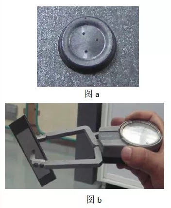
Daily visual inspection. After the rivet-free riveted joint is formed, there will be three small bumps, as shown in Figure a. During the production process, the visual wear state of the three small bumps represents the wear state of the mold. When one of the bumps becomes blurred, it indicates that the mold has started to wear, and it is recommended to replace it; when the two bumps become blurred, it indicates that the mold has been severely worn and must be replaced; when the three bumps become When it is blurred, it indicates that the mold is unusable and the strength of the joint is not guaranteed.
Bottom thickness measurement. The bottom thickness measurement is a unique quality non-destructive testing method without rivet riveting. In daily production, the thickness of the bottom of the joint is measured (shown in Figure b) by a special bottom thickness gauge. The thickness of the bottom should be within 15% of the bottom thickness reference value. It means that the strength of the riveting point can meet the requirements of the product. The bottom thickness measurement measurement is shown in the figure:
Cut test. Cross-section inspection of joints is performed regularly. Take the riveted joint, cut it neatly from the middle, and use the tools such as microscope and measuring software to check the bottom thickness, undercut and neck thickness of the joint (Figure 1.2) and the inclusion state (Figure 3).
The bottom of the riveting point is thick. The bottom thickness value should generally be within plus or minus 15% of the bottom thickness reference value.
Undercut size. The undercut size is required to be f>0.
Neck thickness size. The neck thickness dimension Tn ≥ 0.1T1 is required.
The inclusions are foreign solid impurities entering the riveting point. The inspection requirements are as follows:
The maximum size of inclusions between the two layers is An ≤ 0.2 Ay; (Ay: the cut surface corresponds to the minimum external width dimension of the inclusion position);
On the cutting plane, the number of inclusions per rivet point (size greater than 0.1 Ay) does not exceed 2;
After the measurement, the results of the results are analyzed. The unqualified measurement results must be checked one by one from the aspects of punching pressure, convex and concave mold wear, and sheet thickness, and corresponding rectification measures should be formulated.
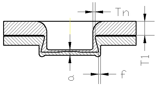
Figure 1 cutaway surface
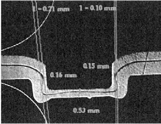
Figure 2 section measurement chart

Figure 3 Schematic diagram of the inclusion after cutting
Staged damage test
For mass production, a staged damage test should be carried out, and the general damage cycle is about half a year. After the rivet riveting is completed on the body assembly, the test sample is cut according to a certain specification; or the plate of the same material and thickness is cut, and placed on the mold in a prescribed manner, and the rivet-free connection is formed to form an inspection. Prototype. Then, a destructive test was carried out, the joint strength was measured, and the joint quality state was evaluated. The damage test method is the same as the test when selecting parameters.
5. Conclusion
In summary, the rivet-free riveting is a cold-working point-joining technology that has been widely used in the automotive industry. In the future, the automotive industry will continue to develop in the direction of composite and lightweight, without the use of rivet riveting technology. Features make it better suited to this development.
Yangzhou Chengde (YC) is one of the best pipe manufacturers in the world, and the production diameter from 8" to 48" in OD and wall thickness from 9.53 mm up to 140mm. We can produce the A/SA53 steel pipes according to the ASME SA53 and ASTM A53 standards.
Yangzhou Chengde founded in 1988, always insist on innovating and creating excellence. At present, the total assets is 6 billion RMB, the number of staff is 3000 and cover an area of 2080 acres of the Chengde group. Chengde group is the first echelon in national brand on seamless steel pipe and including 4 sections: Jiangsu Chengde incorporated company, Yangzhou Chengde Steel Pipe Co., ltd, Yangzhou Chengde Heavy Industry Co., ltd and Taizhou Chengde Steel Pipe Co., ltd.
Chengde have been working on the research.manufacture and sale of seamless pipe about 30 years, and the advantage of core competence is more prominent by integrate in technical.management and market with PCC.
1 The Piercing and rolling technology of Chengde possesses a number of patents in designing and manufacturing the equipment. The production is efficient and flexible, and the quality is stable.
2 The material grade is complete, and the size range is wide (three produce line can manufacture all non-standard sizes). The Minimum Order Quantity (MOQ) as low as ONE piece, and the date of delivery is short with excellent cost performance.
3 The sales and service team is professional and localize.

Astm A53 Pipe,Sa53 B Pipe,Astm A53 Carbon Steel Pipe,Astm A53 Carbon Steel Tube
YANGZHOU CHENGDE STEEL PIPE CO.,LTD , http://www.chengdepipe.com