As an effective process integration model, parallel engineering has become one of the hotspots in the field of advanced manufacturing technology research. Concurrent engineering is the reconstruction, integration and optimization of the process based on information integration. The implementation of concurrent engineering means that the traditional serial product design and development process is a parallel mode.
The idea of ​​concurrent engineering provides a new idea for CAD/CAM integration research, and makes CAD/CAM develop in the direction of intelligence, integration and networking. The traditional CAD/CAM system is a serial working method. It mainly uses CAD to design the product, converts the CAD data into a format acceptable to CAM, and uses CAM for subsequent work, thus realizing CAD and CAM. Sharing of product information. In a concurrent engineering environment, the CAD/CAM integrated system will take advantage of the principles of concurrent engineering and consider the issues at Other stages of the product lifecycle during the design phase to optimize the product development process. Therefore, in the parallel CAD/CAM integration system, on the one hand, the integration, sharing and exchange of product information will be emphasized; on the other hand, the integration of the process is required, and the role of the person is emphasized. In the parallel CAD/CAM system, the engineers and technicians will carry out the design, engineering analysis and manufacturability and assemblyability evaluation of the design on the unified product model under the support of the computer network. And work on process planning, CNC programming, etc.
In the parallel engineering environment, one of the key and core of CAD/CAM integration is product modeling. Parallel CAD/CAM integration requires a product model that contains information on all phases of the product life cycle. Feature-based product models are a milestone in the development of geometric-based product models because they focus on better technical and production management information for the product; it enables product design work at a higher level . Through feature definition, the inconsistency and redundancy of the internal physical model data and external feature data can be avoided, so it is considered to be the most effective way to solve CAD/CAM integration, and is adopted by many commercial CAD/CAM systems, such as Pro/E, I-Deas, UG, etc. In some commercialized feature-based systems, most of them are characterized by parameterized and variable design of features. The product model provided only reflects the information of activities at a certain stage of the product life cycle, resulting in incomplete product information. Parallel CAD/CAM integrated system requirements for product information.
This paper mainly discusses the problems related to product modeling using feature technology, including description of features, system framework for product modeling with features, etc., to explore ways to achieve effective integration of CAD/CAM under concurrent engineering.
2 Characteristics and expression levels
Since the concept of feature generation, feature technology has made CAD technology a new milestone. Many research institutions, experts and scholars have studied feature technology and defined and classified features from different perspectives. For example, Pratt & Wilson pays attention to the shape description of the feature, and thinks that the feature is a meaningful area on the surface of a part, which is divided into six categories: channel feature, concave feature, convex feature, transition feature, region feature and deformation feature. Shah is defined by the information described by the feature: the feature is a set of information related to the product description. This description is mainly used for the design, manufacture or measurement of the product, and even includes management. According to this, he divides the feature into shape features. Material characteristics, precision features and technical features. There are also some scholars who define specific application areas and geometric descriptions. For example, Erve considers a feature to be a distinctive or unique part of a workpiece, defining a geometric shape for a specific machining process or can be used for clamping. Or measurement and other purposes.
These definitions describe features from different perspectives and levels. In general, in the product parallel development process, for a specific product type, the feature is to describe the product information set or knowledge from a certain level of abstraction in the various stages of the product life cycle. In the product design phase, the designer uses the design features to express the design intent when modeling the product, and describes the construction of the part from a functional perspective. The design features here reflect the functional requirements of the product; on the other hand, the implementation of this function is reflected in a related shape feature in the product geometry model. In the field of machining, manufacturing features are used to describe the portion removed from the part blank, the feature set of which primarily includes holes, grooves, depressions, and the like. As shown in Figure 1, one of the parts shown in Figure 1a can be interpreted as the three removed body features shown in Figure 1b, which will be used to create a part manufacturing description during process planning, such as in Figure 1b. The indicated holes will generally result in a drilling or other hole machining operation.
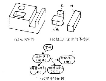
Figure 1 Example of features
As can be seen from the above example, the feature is to describe the product model using the shape feature and the engineering semantics of the application domain related to the shape, as shown in Figure 2, which uses a certain level to characterize the dimension, geometry. /Topological expression and semantic relationship. In the application layer of the feature description, a detailed description and shape feature of the application feature are included, and the application feature refers to the engineering semantics oriented to the application domain, and the hole in FIG. 1 may be used for fastening holes when designing. The shape feature definition layer contains general properties of the shape feature, such as the type of the shape, the main parameters, and the like. In the shape feature description layer, the feature is described by two methods: implicit description and explicit description. The implicit description refers to describing the shape feature details, such as shape parameters, positioning parameters, orientation and generation mode, etc., which can be converted into Explicit description. Explicit description refers to the geometric elements and topological relations that make up the shape features, which are generally expressed by the feature plane attribute adjacency graph. The fourth layer is the geometric description layer, which provides a geometric definition of the description of the feature.
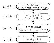
Figure 2 Description of the characteristics
The feature will describe the product information from the above four levels, and finally the part based on the feature description can be expressed by a feature structure tree: its root node represents the part; the second layer represents the main feature of the component; the following layers represent the dependency In the auxiliary feature of the upper layer, Figure 1c is a feature tree representation of part (a).
3 Multi-view transformation and processing of features
For a specific application area, the feature is the carrier that describes the knowledge in the field. In the parallel product development environment, the process of product development is the process of working together from experts in different fields. These experts from different fields will use their own domain knowledge to participate in product development, which means that in feature-based modeling systems, they will use feature sets for their own application domain to characterize them. This reflects the multi-viewability of the feature.
At design time, the designer uses a feature-based approach to build a representation of the product's design features. This process typically involves scanning a 2D sketch outline or instantiating a predefined shape feature to create a feature model and using a record shape. A historical feature tree to record and maintain parent-child relationships between features. The manufacturer is more concerned with the area that is cut from the blank, ie the processing characteristics. In an integrated environment, the processing features should not be input through human interaction, but should be extracted from the product model, including mapping from the feature model or identifying from the solid model. Figures 3c and 3d show an example of a feature's multi-viewability and transformation. In Figure 3c, two rib features are added to a basic block at design time, while Figure 3d is from a manufacturing perspective. A certain volume is removed from the blank to obtain a processing feature of the through groove. The feature modeling system for parallel CAD/CAM integration is required to support multi-view feature modeling and mutual transformation of features between different views.
Shah classifies feature transforms into four categories: direct transform, projection transform, adjacency transform, and conjugate transform. Direct transformations and conjugate transformations make sense for transformations between design features and machining features. An example of these two transformations is shown in Figure 3. Figures 3a and 3b are examples of direct transformations, in which case the design features are identical to the geometry of the manufactured features; Figures 3c and 3d are examples of conjugate transformations, in which case design features and manufacturing features are formed The geometric elements and topological relationships are different.
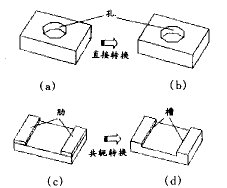
Figure 3 Conversion of multi-view features
In the prototype system we developed for the feature modeling of parallel CAD/CAM integration, the data structure shown in Figure 4 is used to describe the multi-view features. The basic ideas are as follows:
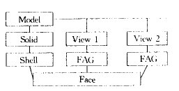
Figure 4 Data structure of multi-view features
(1) The solid model is based on the improved wing-edge description and is divided into six levels: Solid, Shell, Face, Loop, Edge, and Vertex.
(2) The shape feature oriented to the application domain is described by the surface attribute adjacency graph (FAAG) [2], which is equivalent to the open shell in the solid model. The surface attribute adjacency graph is based on the convex and concave features of the edge to describe the relationship between the feature surfaces. ;
(3) the face adjacent graph shares the faces in the solid model;
(4) The system maintains two feature trees at the same time: the design-oriented feature tree and the manufacturing-oriented feature tree. The relationship between the two feature trees describes the relationship between the two views.
The design feature tree records the historical process of the modeling and the dependencies between the features. The root node is a basic modeling block, and the leaf nodes are the shape features attached to it; the root nodes of the manufacturing feature tree represent the parts. The blank, the leaf node is the processed area, that is, the processing characteristics. The two trees establish a feature relationship diagram through the shared face. For example, the feature tree and relationship diagram for designing and manufacturing two views of the parts shown in Figures 3c and 3d are shown in Figure 5.

Figure 5 Figure 3 and Figure 3d feature tree and relationship diagram
Design view feature generation is a method of feature design; manufacturing view feature generation and feature change propagation is an improved incremental feature recognition method. The specific algorithm is as follows:
(1) When the design (manufacturing) feature changes (including addition, deletion, parameter change), the face that has changed due to the change (deleted face or added new face) is recorded;
(2) Finding the processing (design) features associated with the (1) midplane in the feature relationship diagram;
(3) Find sub-features that depend on the features in (1), (2);
(4) Reconstruct the processing (design) feature tree by geometric reasoning and matching, and modify the feature relationship diagram.
The above algorithmic process will be described below with the parts shown in FIG. 6. The parts shown in (1) in the figure have a basic block block (including faces f1, f2, f3, f4, f5, f6, f10) and ribs Dr1 (including faces f2, f3, f7) from the design field of view. , f8, f9); from the manufacturing field of view, there is a blank body Base (including faces f1, f2, f3, f4, f5, f8), two steps Mst1 (including faces f6, f7) and Mst2 (including face f9) , f10). When adding a rib Dr2 to the design, the changed quilt is
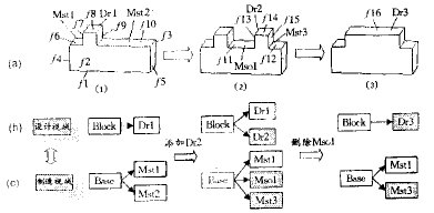
Figure 6 Example of design view and manufacturing view feature transformation
4 Feature modeling prototype system for parallel CAD/CAM integration
Based on the foregoing principles, we developed a feature modeling prototype system for parallel CAD/CAM integration. The goal of this system is to provide a feature-based product modeling environment for parallel CAD/CAM integration systems that requires support for multi-view feature modeling and transformation.
The prototype system was developed under the AutoCAD R14 using the ObjectARX tool. The specific ideas are as follows:
a. Use Auto CAD's graphical interface, graphical display function and command interaction system to save some basic work;
b. Because Auto CAD solid modeling function (including ARX secondary development capability) has many limitations, it abandons the original solid modeling function of Auto CAD, and develops a solid modeling core with improved wing edge structure (currently only supports polyhedral modeling) ).
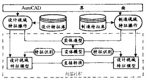
Figure 7 Feature modeling prototype system framework
The structure of the entire prototype system is shown in Figure 7. The product modeling process under the prototype system is as follows:
(1) Feature design: In the design field of view, using the design feature modeling, the resulting model contains the referenced design feature semantic information, geometry/topology information, and corresponding dimensions, tolerance information, etc.
(2) Direct conversion and recognition of processing features: Using the above-mentioned incremental recognition-based method, in the representation of the product's design features, the directly convertible features are directly converted, otherwise the entity representation of the product is combined with the design feature tree identification. Processing characteristics;
(3) Establish a product model for manufacturing: process planning for the identified machining features, including determining the machining method, selecting the machine tool, selecting the tool, and determining the machining process.
(4) When the product model changes in the manufacturing horizon, the aforementioned incremental recognition-based approach will also be used to propagate this change from the manufacturing horizon to the design horizon.
5 Conclusion
A key and core issue in parallel CAD/CAM integration is the creation of a unified product model. Because the feature has both information of shape and functional semantics, feature-based product modeling becomes an effective way to realize information integration in parallel CAD/CAM systems. The feature modeling technology introduced in this paper makes a meaningful discussion on the information integration of parallel CAD/CAM systems:
(1) In the parallel CAD/CAM integration environment, the feature is to describe the product information set or knowledge at a certain level of abstraction in each phase of the product life cycle, which has both shape and functional semantic information;
(2) In the parallel CAD/CAM integrated environment, the feature modeling system should support multi-view feature modeling and transformation. A feasible method presented in this paper is to describe the feature by using the feature attribute adjacency graph based on the edge convexity and concave properties. , expressing the relationship of features between different views through a feature relationship diagram;
(3) The paper proposes an improved incremental feature recognition method and a direct mapping method to maintain the relationship between different views.
The prototype system based on the principle of the text has been basically established, and further improvements are needed in the following aspects:
a. Propagation of constraints and maintenance of the validity of features when performing feature transformations between different views;
b. Further improve the function of solid modeling to enable support for persistent topology identification
Gold Mirror Stainless Steel,Color Mirror Sheet,Mirror Color
Hong-Steel Co., Ltd. , http://www.qiyistainlesssteel.com