(1) Volumetric
| classification | Reciprocating | Rotary | | Fundamental | The reciprocating action of the piston in the cylinder causes the internal volume of the cylinder to be repeatedly changed to suck and discharge the fluid | When the rotor or rotating part in the casing rotates, the working volume between the rotor and the casing changes, thereby drawing in and discharging the fluid. | | Animated demo | 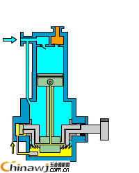 | 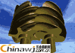 | | Product illustration | Piston pump | Gear pump |
(2) Blade back to top
The main structure of the vane pump and fan is a rotatable, bladed impeller and a fixed casing. The fluid is energized by the rotation of the impeller to obtain energy.
Depending on the flow of the fluid, they can be subdivided into the following categories:
| classification | Centrifugal | Axial flow | Mixed flow | Tubular | | Fundamental | The centrifugal force generated when the impeller rotates at high speed causes the fluid to obtain energy | The extrusion propulsion of the rotating blades causes the fluid to gain energy and raise its pressure and kinetic energy. | Centrifugal and axial flow mixtures | Principle and centrifugal | | Structure demonstration | Work component | the whole frame | Work component | the whole frame | Work component |
overall
structure
| Work component | the whole frame | 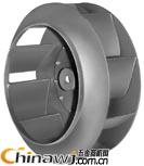 | 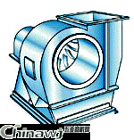 | 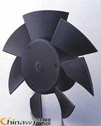 | 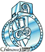 | See the next section (omitted) | See the next section (omitted) | | Product illustration | Centrifugal fan for central air conditioning | Axial flow pump for central air conditioning or cold storage | Mixed flow pump | Household air conditioner indoor fan |
The second section of the pump and fan works back to top
First, the working principle of centrifugal pump and fan back to top
| working principle | The centrifugal force generated when the impeller rotates at a high speed causes the fluid to obtain energy, that is, after the fluid passes through the impeller, both the pressure energy and the kinetic energy are increased, so that it can be transported to a high place or a distant place. The impeller is housed in a spiral outer casing. When the impeller rotates, the fluid flows axially, then turns 90 degrees into the impeller flow path and flows radially. The impeller rotates continuously, creating a vacuum at the impeller inlet so that the fluid is continuously drawn and discharged by the pump. | | Pattern performance | 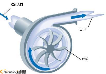 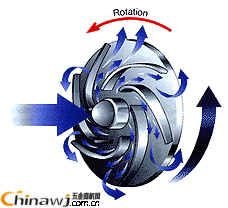 | | The overall structure | 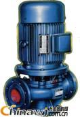 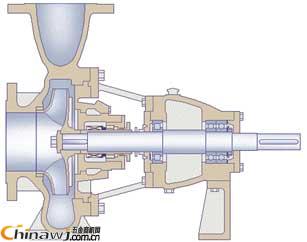 | |
two. Axial flow pump and fan working principle back to top
The working principle of the axial flow pump and the fan is that the structure of the fan is as shown in the left two figures, and the third figure is the structure diagram of the axial flow pump (click to enlarge).
| working principle | The extrusion propulsion force of the rotating blade causes the fluid to obtain energy and raises its pressure and kinetic energy. The impeller is installed in a cylindrical (fan is conical) pump casing. When the impeller rotates, the fluid flows axially into the blade channel. After the energy is obtained, it flows out in the axial direction. Axial flow pumps and fans are suitable for high flow and low pressure, and are often used as circulating water pumps and blower fans in refrigeration systems. | | Pattern performance | 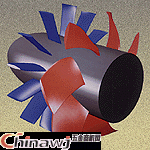 |
three. Working principle of cross flow fan back to top
| working principle | Due to the development of air conditioning technology, there is a need for a small fan with a small amount of air, low noise, proper head and easy installation with the building. A cross-flow fan is a new type of fan that meets this requirement. | | Pattern performance |  |
The main features of the cross-flow fan in recent years are as follows:
(1) The impeller is generally a multi-leaf type of forward vane, but the two end faces are closed.
(2) The width b of the impeller is not limited, when the width is increased. The traffic also increases.
(C) The cross-flow fan is not like the centrifugal fan is open on the side plate of the casing to make the airflow axially enter the phoenix machine, but the casing is partially opened to allow the airflow to enter the fan directly. The airflow traverses the blade twice. Some cross-flow fans add stationary guide vanes to the inner edge of the impeller to improve airflow.
(4) In terms of performance, the full-pressure coefficient of the cross-flow fan is larger. The performance curve is camel-type, and the efficiency is low, generally about 30% to 50%.
(5) The air inlet and the air outlet are both rectangular and easy to match with the building. There are still many problems to be solved in the cross-flow fan. In particular, the geometry of the various parts has a major impact on its performance. The imperfect structure is not working at all, but the range of use of small cross-flow fans is steadily expanding.
Fourth, other commonly used pumps back to top
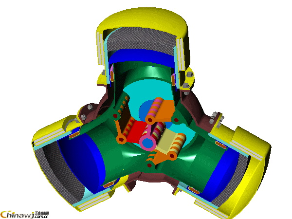
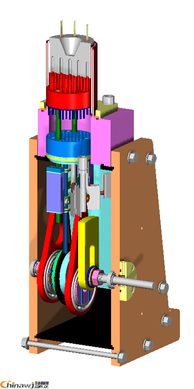
1, the working principle of the reciprocating pump
| working principle | The rotation of the eccentric shaft drives the movement of the piston through the connecting rod device to convert the circumferential rotation of the shaft into the reciprocating motion of the piston. As the piston reciprocates continuously, the pump's water absorption and pressure water processes alternate continuously. | | Pattern performance | 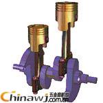 | | The overall structure | | | Special structure example |
|
2, water ring vacuum pump back to top
| working principle | The impeller of the water ring vacuum pump blade is eccentrically mounted in a cylindrical pump casing. Inject a certain amount of water into the pump. When the impeller rotates, the water is pumped to the pump casing to form a water ring, and the inner surface of the ring is tangent to the impeller hub. Since the pump casing is not concentric with the impeller, the intake space 4 between the right half hub and the water ring is gradually enlarged, thereby forming a vacuum, and the gas enters the intake space of the pump through the intake pipe. The gas then enters the left half, and as the volume between the hub rings is gradually compressed, the pressure is increased, so that the gas is discharged to the outside of the pump through the exhaust space and the exhaust pipe. | | Pattern performance | 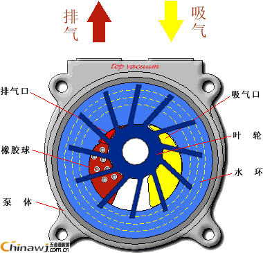 |
3, Roots vacuum pump working principle back to top
| working principle |
The Roots pump works like a Roots blower. Due to the continuous rotation of the rotor, the pumped gas is sucked from the intake port into the space v0 between the rotor and the pump casing, and then discharged through the exhaust port. Since the v0 space is fully closed after inhalation, the gas is not compressed and expanded in the pump chamber. However, when the top of the rotor turns over the edge of the exhaust port and the v0 space communicates with the exhaust side, since the gas pressure on the exhaust side is high, a part of the gas is returned to the space v0, so that the gas pressure suddenly increases. When the rotor continues to rotate, the gas exits the pump.
In general, Roots pumps have the following characteristics:
Large pumping speed over a wide range of pressures;
â— Quick start, can work immediately;
â—Not sensitive to dust and water vapor contained in the pumped gas;
â—The rotor does not have to be lubricated, and there is no oil in the pump chamber
â—The vibration is small, the rotor dynamic balance condition is good, and there is no exhaust valve;
â—The driving power is small, and the mechanical friction loss is small;
â— Compact structure and small footprint;
â— Low operating and maintenance costs.
Therefore, Roots pumps are available in the metallurgical, petrochemical, paper, food, and electronics industries.
To a wide range of applications.
| | Pattern performance | 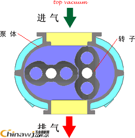 |
4. Working principle of rotary vane vacuum pump back to top
| working principle | The rotary vane vacuum pump (referred to as the rotary vane pump) is an oil-sealed mechanical vacuum pump. Its working pressure range is 101325~1.33×10⁻²(Pa), which belongs to low vacuum pump. It can be used alone or as a foreline pump for other high vacuum pumps or ultra high vacuum pumps. It has been widely used in the production and scientific research departments of metallurgy, machinery, military, electronics, chemical, light industry, petroleum and medicine.
The rotary vane pump is mainly composed of a pump body, a rotor, a rotary vane, an end cover, a spring and the like. A rotor is eccentrically mounted in the cavity of the rotary vane pump, the outer circumference of the rotor is tangent to the inner surface of the pump chamber (there is a small gap between the two), and two rotor blades are mounted in the rotor slot. When rotating, the top end of the rotary vane is kept in contact with the inner wall of the pump chamber by the centrifugal force and the tension of the spring, and the rotation of the rotor drives the rotary vane to slide along the inner wall of the pump chamber.
The two rotary vanes divide the crescent-shaped space enclosed by the rotor, the pump chamber and the two end caps into three parts A, B and C. When the rotor rotates in the direction of the arrow, the volume of the space A communicating with the suction port is gradually increased, and is in the process of suction. The volume of the space C communicating with the exhaust port is gradually reduced, and is in the process of exhausting. The volume of the centered space B is also gradually decreasing and is in the process of compression. Since the volume of the space A is gradually increased (i.e., expanded), the gas pressure is lowered, and the external gas pressure at the inlet of the pump is stronger than the pressure in the space A, so that the gas is sucked. When space A is isolated from the suction port, that is, to the position of space B, the gas begins to be compressed, the volume is gradually reduced, and finally communicates with the exhaust port. When the compressed gas exceeds the exhaust pressure, the exhaust valve is pushed away by the compressed gas, and the gas is discharged to the atmosphere through the oil layer in the oil tank. Continuous operation of the pump achieves the purpose of continuous pumping. If the exhausted gas passes through the air passage and is transferred to another stage (low vacuum level), it is pumped away by the low vacuum stage, and then compressed by the low vacuum stage and discharged to the atmosphere, which constitutes a two-stage pump. At this time, the total compression ratio is borne by two stages, thereby increasing the ultimate vacuum. | | Pattern performance | 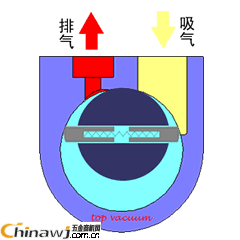 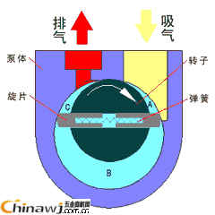 |
5, the working principle of the gear pump
| working principle | The gear pump has a pair of intermeshing gears. As shown, the gear drive wheel is fixed on the drive shaft. One end of the shaft extends out of the casing and is driven by the prime mover, and the other gear driven wheel is mounted on the other shaft. The gear rotates. At the same time, the liquid enters the suction space along the suction pipe, and is squeezed by the two gears along the upper and lower casing walls to the discharge space to merge (before the teeth mesh with the teeth), and then enters the pressure pipe for discharge. | | Pattern performance |  |
7, screw pump working principle back to top
| working principle | A screw pump is a rotary pump that uses a screw to mesh with each other to draw in and discharge liquid. The rotor of the screw pump consists of an active screw (which can be one or two or three) and a driven screw. The driving screw rotates in the opposite direction with the driven screw, the threads mesh with each other, the fluid enters from the suction port, and is pushed forward by the spiral axial direction to the discharge port. This pump is suitable for high pressure and low flow. In the refrigeration system, it is often used as an oil pump for conveying bearing oil and governor oil. | | Pattern performance | 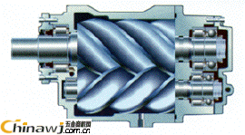 |
8. Jet pump working principle back to top
| working principle | The high-pressure working fluid 7 is sent from the pressure pipe to the working nozzle 6, and after the nozzle, the pressure energy becomes high-speed kinetic energy, and the liquid (or gas) around the nozzle is taken away. At this time, the nozzle outlet is formed at a high speed to cause a vacuum in the throat suction chamber 5 of the diffusion chamber 2, so that the pumped fluid 8 continuously enters the working fluid 7, and then the pressure is slightly raised through the diffusion chamber. Due to the continuous injection of the working fluid, the suction chamber continues to maintain a vacuum, so that the fluid is continuously sucked and discharged. The working fluid can be high pressure steam or high pressure water. The former is called a steam jet pump, and the latter is called a water jet aspirator. Such pumps are relatively rare in refrigeration systems.
| | Pattern performance | 
|
|
 Editor: (Hardware Business Network Information Center) http://news.chinawj.com.cn

