The structure of the plastic inner sleeve is shown in Figure 1. The material is PP, the color is black, and the inner surface is high gloss. Appearance quality requirements are free of defects such as lack of material, bubbles, white, shrink marks and draping.

Figure 1 Plastic lining product structure
1. Product structure process analysis
From the structural drawing of the plastic inner sleeve, the parting surface of the mold is known.
There are three options to choose from, as shown in Figure 2. However, in either case, the side angle of 99° on the side of the product and the side groove of 0.8 mm width must be demolded by a side-splitting core pulling mechanism.

Figure 2 Three options for the selection of the parting surface
(1) The solution a core 2 is fixed on the movable template, which is favorable for the plastic part to be retained on the movable mold core after molding, and the ejector pin is used for ejector products. However, when the A-type is moved backward to move the mold, the flap slider must be separated first, and the flap slider is set in the fixed mold portion. In order to drive the slider for lateral splitting and splitting, the mold structure must first be typed on the fixed mold. The splitting process is used to make the inclined guide column move the flap and slide the slider for the parting action. Although this structure can complete the demolding process, it complicates the overall structure of the mold.
(2) Scheme b is divided into A parting surface, and the flapping slider is set in the moving mold, which is beneficial to the oblique guiding column when it is set in the fixed mold, and the inclined guiding column is slidably closed by the opening of the parting surface. The block is used as a parting action. This is the simplest and most practical structural form of the lateral splitting core pulling mechanism. However, the core 2 is fixed to the fixed mold. It is difficult to ensure that the plastic part remains in the slider and is detached from the core when the mold is opened. When the shrinkage force of the plastic part on the core is large, the entire slider is even left in the fixed mold, so that the demoulding process fails. . Although the spring pin is added on the parting surface, the mold can be forced to separate from the A parting surface, and the slider is left in the moving mold for lateral classification, but the mold adjustment process also has certain difficulty.
(3) Scheme c Partially splitting the B-part, the core 2 and the flap slider can be placed in the movable part. The structure can ensure that the plastic part remains on the movable mold core, and the lateral split core pulling mechanism is simple and practical. However, the appearance of the plastic parts will retain the marks of the type. Since the inner cover part requires a high gloss surface, the outer surface is assembled with other parts and does not affect the overall appearance of the product, and the trace of the appearance of the plastic part is acceptable. Therefore, option c is the optimal structural form of the mold.
In order to facilitate the setting of the pouring system, the side gate is used for feeding, and the mold adopts a structure of two cavities.
2. Mold structure design
The mold structure assembly is shown in Figure 3.

image 3
1, 9, 10, 14, 18, 23, 26, 30, 32. Hexagon head screws
2. Guide post 3. Guide sleeve 4. Dynamic model core insert 5. Fixed model cavity insert
6. Top rod 7. Positioning ring 8. Pouring sleeve 11. Thimble 12. Fixed mold seat plate
13. Fixed template 15. Moving template 16. Reset rod 17. Support column 19. Thimble fixing plate
20. thimble pad 21. Movable seat plate 22. Support block 24. Flat end set screw
25. Limit steel ball 27. Valve slider 28. Compression spring
29. inclined guide post 31. locking block
(1) Design of the molded part The cavity part of the mold is mainly composed of a fixed cavity insert, a flap slider and a movable mold core insert. The fixed cavity insert and the movable mold core insert are respectively fixed on the fixed plate and the movable plate by the hexagon socket head screws. The material is made of alloy steel S136 for the mold, and the hardness of the cavity surface can reach 58-62HRC after heat treatment. After polishing, the mirror surface light can be achieved, and the surface roughness value is Ra ≈ 0.4 μm to meet the high gloss surface requirements of the surface of the product after molding.
(2) Design of the lateral split core pulling mechanism The structure of the lateral split core pulling mechanism of the mold is shown in Fig. 4.
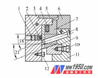
1. Flat end set screw 2. Limit steel ball 3. Moving plate 4. Compression spring
5. Dynamic model core insert 6. Fixed model cavity insert 7. Flap joint slider 8. Slant guide post
9. Locking block 10. Hexagon head screw 11. Set template 12. Limit screw
The inclination angle of the inclined guide column is α = 18°, and the inclination angle of the matching slope of the locking block and the flap slider is β = α + 3 ° = 21 ° to ensure that the locking block precedes the inclination when the mold is opened. The guide post leaves the flap slider, and when the mold is closed, the lock block finally locks the position of the flap slider to withstand the injection pressure of the melt. The guiding groove of the flap sliding slider is formed by directly forming a T-shaped groove on the movable template, which makes the mold simpler. In order to prevent the valve block from being misaligned after the mold is closed, a tapered surface positioning structure is formed on the contact surface of the flap slider, as shown in FIG. 5, and the taper angle is 45°.
(3) Design of the gating system The mold gating system consists of a main channel, a runner, a gate and a cold hole. The main flow channel is directly formed by the sprue bushing, and the end of the main flow channel adopts a reverse cone-shaped cold material hole to collect the forward cold material of the melt during the injection molding process, and the main channel can be pulled out and left on the movable mold after the mold is opened. Then, the top rod is ejected to release the mold. The runner is opened on the parting surface and has a circular cross section to ensure a good flow effect of the melt.
A latent gate feed to one side of the fixed mold is used. The latent gate can automatically cut off and separate the plastic part from the casting system when the workpiece is ejected after the mold is opened.
(4) The mold temperature control system of the mold temperature control system mold,
The fixed mold part opens a circulating cooling water channel on the fixed template, and the movable mold part opens a circulating cooling water channel on the movable template to control the mold temperature within the required temperature range, thereby shortening the molding cycle on the basis of ensuring product quality. The exhaust system of the mold mainly utilizes the gap between the slider and the core to exhaust.
3. The working process of the mold
The mold is clamped and mounted on a horizontal injection machine. Under a certain injection pressure, the plastic melt is injected into the cavity of the mold through the pouring system through the nozzle, and the gas in the cavity is discharged from the gap between the valve and the core to complete the injection molding process. process. When the mold is opened, the fixed mold portion is fixed on the fixed mold coupling plate of the injection machine, and the movable mold portion is moved backward. In this process, the T-shaped groove on the movable mold drives the flap-closing slider to perform lateral splitting movement along the inclined guide post. The compression spring in the flap slider produces an instantaneous initial force upon sliding that prevents the flap slider from becoming stuck before moving. The position of the flap slider is limited by the limit steel ball and is assisted by the limit screw. The ejector ejecting mechanism on the mold then ejects the mold from the driven mold core insert. When the mold is closed, the ejection mechanism is reset by the reset lever to complete a molding cycle.
High pressure Air compressors have a multitude of uses for leisure and maintenance at home or in businesses to get work done efficiently and safely.
Portball Air Compressor pump for Blowing up balloons or inflatable products
Adding air to tires on bikes and on vehicles
Cleaning crevices and tight spaces on equipment or other durable items with directed air pressure
Using various pneumatic tools for home projects
Pintball air compressor for recharge paintball rifle gun
air compressor gun Features:
1.This 300bar air compressor pump Long life, safety explosion-proof.
2.This portable air compressor Integral cylinder head without external gas path pipe.
3.The 300bar compressor with built-in water separation system, is not easy to carbon deposit.
4.Our Pcp Air Compressor all with Built in integrated oil-water separation, imported super wear piston ring.
Air Compressor
Air Compressor,Pcp Air Compressor,Paintball Air Compressor,High Pressure Air Compressor
SHIJIAZHUANG TOPA TRADING CO., LTD. , http://www.topahydraulic.com